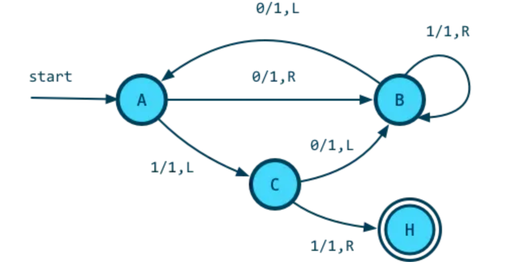
A Turing Machine can be visually represented by a state diagram.
Example
Warning
No conventions exist. This convention attempts to model VCAA, however, they use i/j:k instead of i/j,k.
 Components:
- each circle letters represents a unique state
- arrows represent possible state transitions (e.g. C can transition into B or H)
- labels (e.g. 0/1,R) represent the scanned symbol that causes a particular transition (e.g. 0) followed by a slash /, followed by the subsequent behaviours of the machine - set the cell to 1 then move tape right.
- for example, going out from B:
0/1,Lgoing to A. This means that if when we read 0 on the tape and our current state is B, we transition to A and perform1,L(set current cell to 1, and move left)1/1,Rgoing back onto B. This means that when we read 1 on the tape and our current state is B, we transition to B and perform1,R(set current cell to 1, and move right)
- for example, going out from B:
- the double bordered circle (H) denotes one of the final states, meaning the machine halts
- intuitively if no state has outgoing transitions then the state is also one of the final states